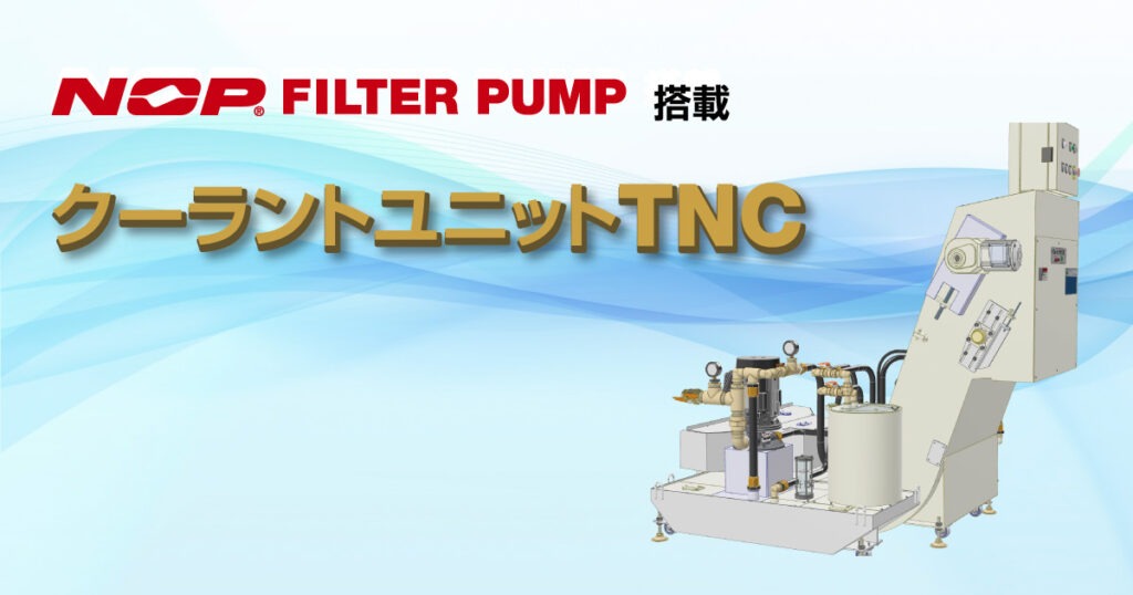
Coolant Unit Dedicated to BT30 Machining Center
FEATURES
Space and Resource savings
Compact design with a tank capacity of 143 L circulating in a small tank, which takes less space than conventional drum-type units.
Minimized, Filtrated and flushed coolant fluid keeps the tank clean, no sludge accumulation, no bacteria propagated and reduces coolant deterioration.
Reduced tank maintenance and Improved work efficiency
A double-decker scraper conveyor and NOP FILTER PUMP filter all coolant and transfer it in circulation.
The tank is designed to prevent sludge accumulation inside the tank. Maintenance such as tank cleaning is reduced and workability is improved.
Low processing defect and Upward processing accuracy
All coolant transferred to the machine is filtered by NOP FILTER PUMP to supply clean liquid.
Prevents seating errors, chock stops, and workpiece scratches caused by chips.
MECHANISM OVERVIEW
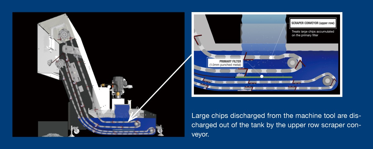
Primary Filtration
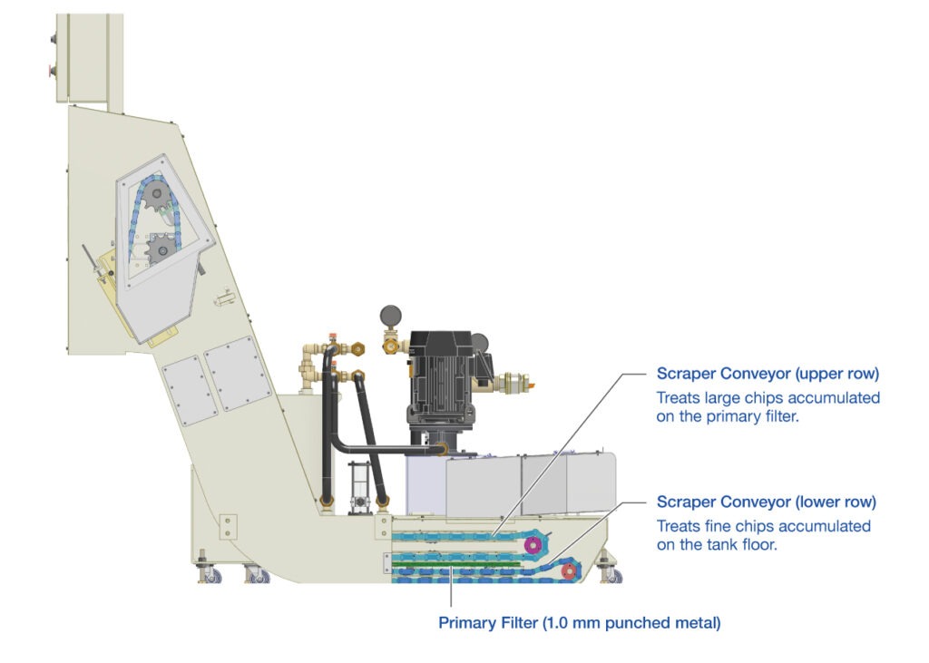
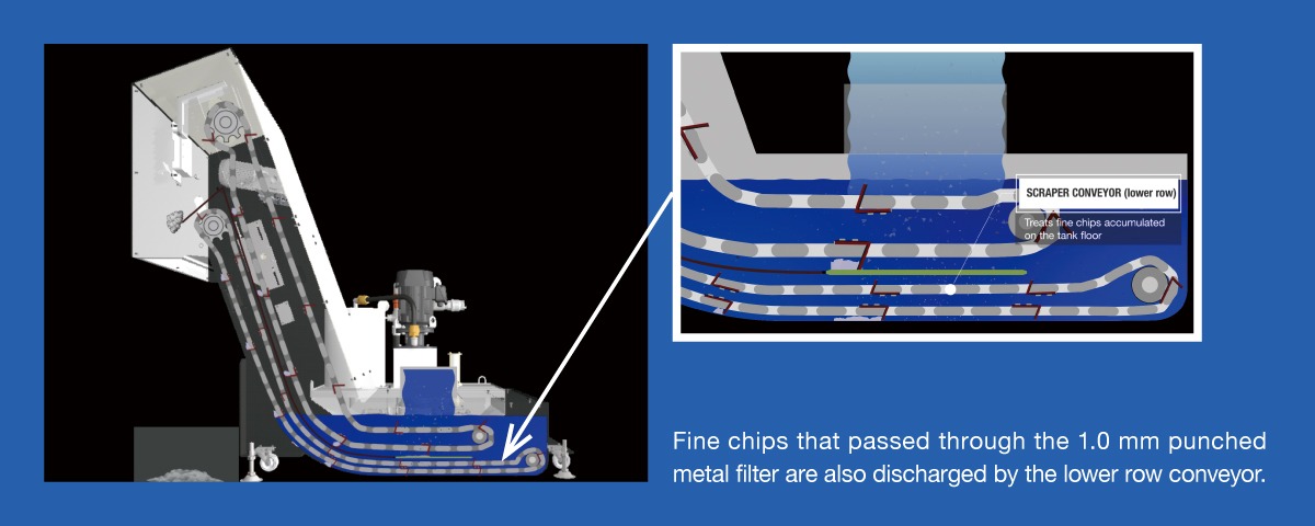
Large chips discharged from the machine are discharged out of the tank from the upper row of the double-decker scraper conveyor. Fine chips that passed through the 1.0mm punched metal filter are also discharged by the lower row conveyor.
Handles fine chips
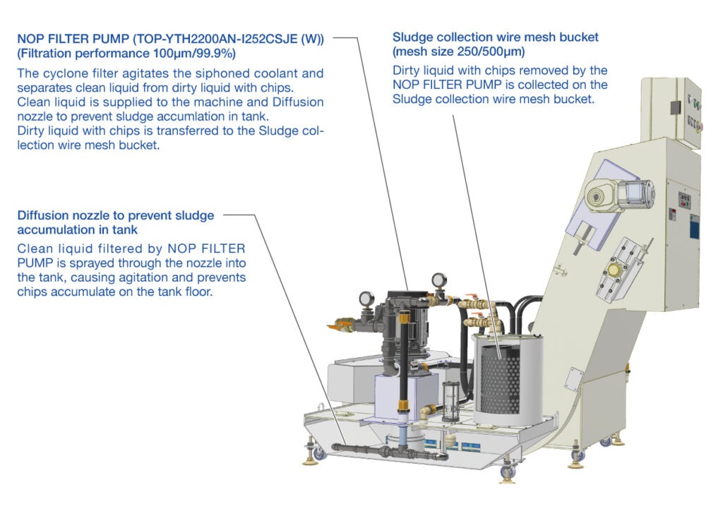
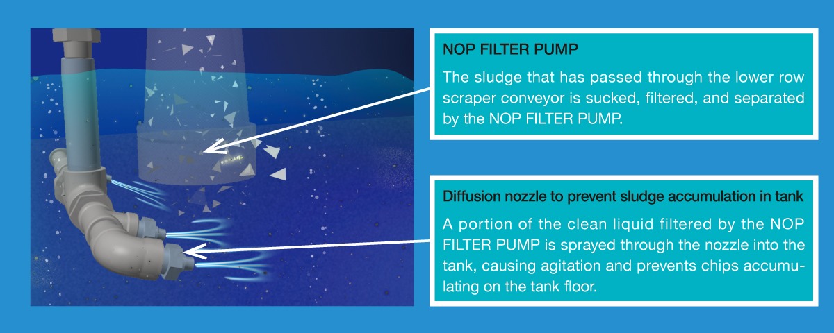
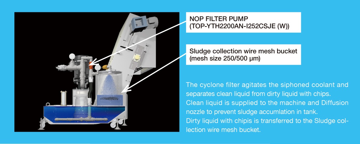
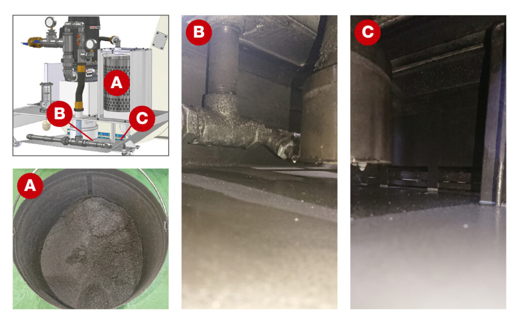
The sludge that has passed through the lower row of the double-decker scraper conveyor is sucked, filtered, and separated by the NOP FILTER PUMP.
Clean liquid is supplied to the machine and Diffusion nozzle to prevent sludge accumulation in tank.
Dirty liquid with chips is transferred to the Sludge collection wire mesh bucket.
Circulates clean coolant
As a mechanism to prevent sludge accumulation in the tank, a diffusion nozzle forcibly circulate the sludge to the NOP FILTER PUMP , and collects it by re-injecting it.
Contrivance of coolant unit TNC
EXPLANATORY VIDEO
INSTALLATION EXAMPLE
Conveyor post-loading specification
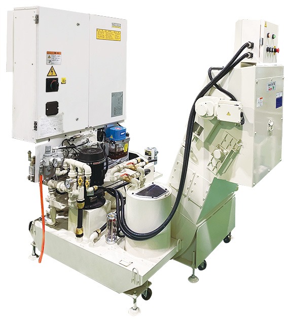
Conveyor left with CTS specification
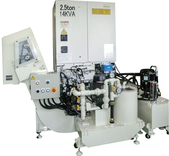
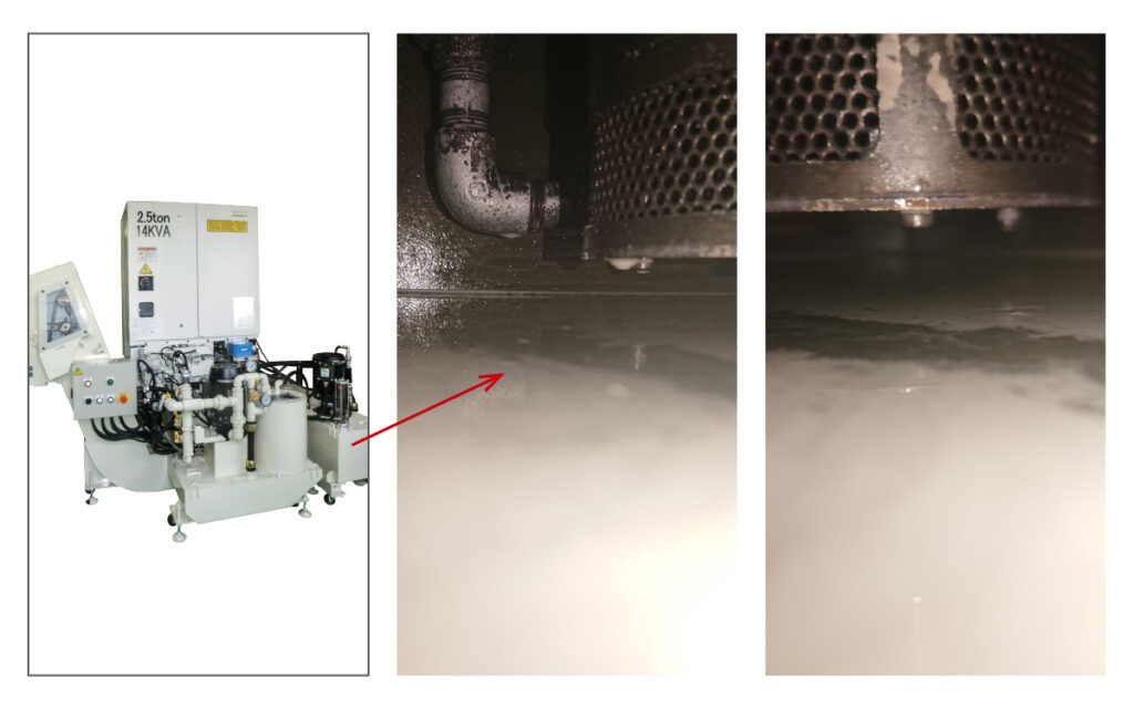
Tank condition after 12 months of use
Introduction example of aluminum processing machine
Tank condition after 12 months of use (4,000 kg of chips discharged from the processing machine)
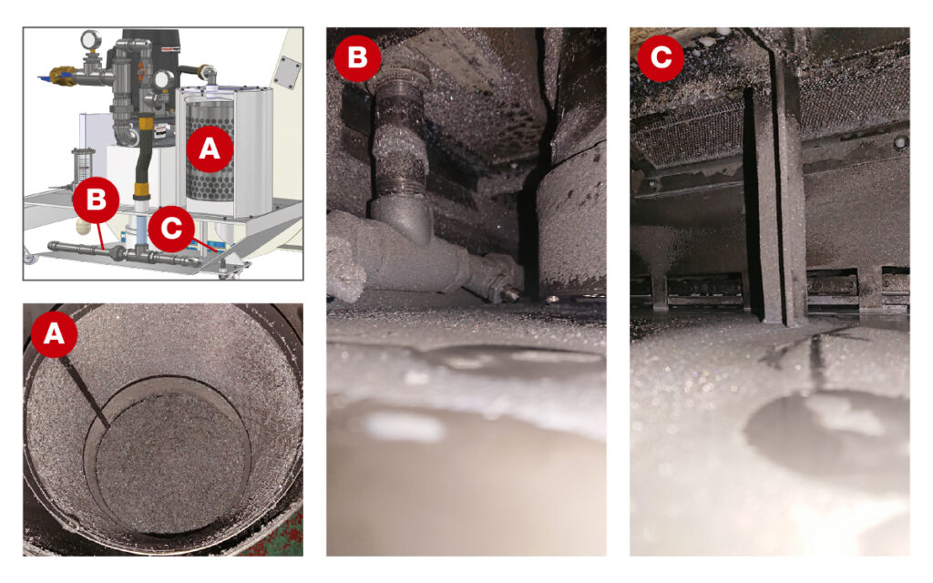
Tank condition after 12 months of use (4,000 kg of chips discharged from the processing machine)
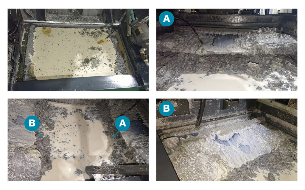
Tank equipped with pump for CTS/through spindle
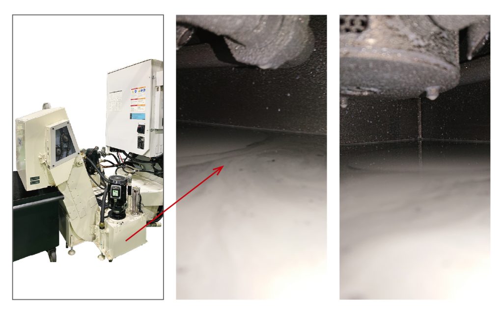
Introduction example of cast metal processing machine
Tank condition after 12 months of use, the inside of the primary tank after draining
Tank condition after 12 months of use, the inside of the secondary tank after drainage
DIMENSIONS/SPECIFICATIONS
Typical Drawing
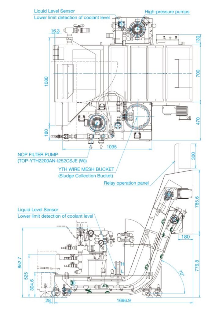
Typical Specifications
◆ Conveyor specifications (Scraper)
| Conveyor speed | 2.40 m/min (50 Hz) 2.88 m/min (60 Hz) |
| Conveyor chain | RF2050R4LA2:With scraper every 8 links RF2060R4LA2:With scraper every 8 links |
| Safety device | Current Relay |
| Coolant capacity | Primary tank 143 ℓ (effective capacity 84 ℓ): 94 ℓ in conveyor (effective capacity 54 ℓ) 49 ℓ in tank (effective capacity 30 ℓ) Secondary tank 23 ℓ: Total primary and secondary capacity 166 ℓ |
| Power Supply | AC200/200 V 50/60 Hz |
| Electrical component | Up to relay operation panel |
| Coating | Our standard color (Munsell 5Y8/1.5 with luster) Urethane coating |
◆ Conveyor Motor Specifications/Reduction Gear
| Motor model Number and Specifications | TMHF-02-240-001 0.2 kW 1/240 With load detection (current relay) |
| Rotational Speed | 6.3/7.5 rpm (50/60Hz) |
| Current | 1.24/1.1/1.11 A (200/200/220 V) (50/60/60 Hz) |
◆ NOP FILTER PUMP (TOP-YTH2200AN-I252CSJE (W)) Motor Specifications
| Pump model | NOP FILTER PUMP (TOP-YTH2200AN-I252CSJE (W)) |
| Motor model Number and Specifications | IKH3-FCKLA21E (2.2 kW/2P) |
| Flow Rate | 250 ℓ/min (Contaminant Drain Port 30~60 ℓ/min) |
| Current | 8.6/8.4/7.6 A (200/200/220 V) (50/60/60 Hz) |
| Filtration Rating (Nominal) | 100 μm/99.9% (50 μm/90%以上) |
◆ Medium pressure pump, motor Specifications (option with CTS)
| Pump model | YTH1500A3-S216EVD20C or S216CVD20 |
| Motor model Number and Specifications | IKH3-FCKLA21E (1.5 kW/4P) |
| Maximum Pressure | 2.0 MPa |
| Flow Rate | 24.0/28.8 ℓ/min (50/60 Hz) |
| Current | 6.8/6.4/6.0 A (200/200/220 V) (50/60/60 Hz) |
◆ YTH WIRE MESH BUCKET (Sludge Collection Bucket)
| Specifications | External dimensions: φ250 × 300 mm Wire mesh (Lower layer/Upper layer): 250/500 μm |
※A lineup is available to meet your needs, such as conveyor discharge direction, medium to high pressure through-pump, etc.


